Current limiting reactor
In electrical engineering, current limiting reactors can reduce short-circuit currents, which result from plant expansions and power source additions, to levels that can be adequately handled by existing distribution equipment.[1] They can also be used in high voltage electric power transmission grids for a similar purpose. In the control of electric motors, current limiting reactors can be used to restrict starting current or as part of a speed control system.
History
Current limiting reactors, once called current limiting reactance coils, were first presented at a Meeting of the Society of Mechanical, Electrical, and Steam Engineers, Boody House, Toledo, Ohio, in 1915.[2] The inventor of the current limiting reactance coil was Vern E. Alden who filed the patent on November 20, 1917 with an issue date of September 11, 1923. The original assignee was Westinghouse Electric & Manufacturing Company.[3]
How it works
Where the prospective short circuit current in a distribution or transmission system is calculated to exceed the interrupting rating of the associated switchgear, a current limiting reactor may be selected. The inductive reactance is chosen to be low enough for an acceptable voltage drop during normal operation, but high enough to restrict a short circuit to the rating of the switchgear. The amount of protection that a current limiting reactor offers depends upon the percentage increase in impedance that it provides for the system.[4]

The main motive of using current limiting reactors is to reduce short-circuit currents so that circuit breakers with lower short circuit breaking capacity can be used. They can also be used to protect other system components from high current levels and to limit the inrush current when starting a large motor.[5]
Construction
It is desirable that the reactor does not go into magnetic saturation during a short-circuit, so generally an air-core coil is used. At low and medium voltages, air-insulated coils are practical; for high transmission voltages, the coils may be immersed in transformer oil. Installation of air-core coils requires consideration of the magnetic field produced by the coils, which may induce current in large nearby metal objects. This may result in objectionable temperature rise and waste of energy.[6]
Line reactor
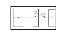
A line reactor is an inductor wired between a power source and a load. In addition to the current limiting function, the device serves to filter out spikes of current [7] and may also reduce injection of harmonic currents into the power supply. The most common type is designed for three-phase electric power, in which three isolated inductors are each wired in series with one of the three line phases.[8] Line reactors are generally installed in motor driven equipment to limit starting current, and may be used to protect Variable-frequency drives and motors.:[9])
See also
References
- ↑ Simpson, James. "The how and why of current-limiting reactors". Highbeam Business. EC&M Electrical Construction & Maintenance. Retrieved 17 September 2012.
- ↑ view=image; size=100;seq=5;num=1 "The Use of Current-Limiting Reactors" Check
|url=value (help). Society of Mechanical, Electrical, and Steam Engineers. Westinghouse Electric Mfg. Company. Retrieved 18 September 2012. - ↑ Alden, Vern. "USPTO". Current Limiting Reactance Coil. Westinghouse Electric and Manufacturing Company. Retrieved 17 September 2012.
- ↑ "Current Limiting Reactors: Technical Overview and Measurement Procedures" (PDF). NWL. Retrieved 17 September 2012.
- ↑ "Quality Power". Retrieved 17 September 2012.
- ↑ "Electrical Transmission and Distribution Reference Book", Westinghouse Electr Corporation, Pittsburgh PA , 1950 pp. 133-135
- ↑ http://www.myronzucker.com/linereactorpg1.html What is a Line Reactor?
- ↑ http://www.cosphi.com/line-load-reactor-applications.html Line reactor configurations
- ↑ http://ecmweb.com/mag/electric_line_reactors_vfds/