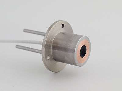
Gardon gauge

A Gardon gauge or Circular-foil gauge is a heat flux sensor primarily intended for the measurement of high intensity radiation. It is a sensor that is designed to measure the radiation flux density (in watts per metre squared) from a field of view of 180 degrees. The most common application of Gardon gauges is in exposure testing of sample materials for their resistance to fire and flames.
Explanation
While heat flux sensors can be made according to various designs, the sensor of a Gardon gauge consists of a foil connected to the sensor body at its external radius, and connected to a thin wire at the center, named after its originator Robert Gardon.[1] The foil center and side are the hot- and cold joint of a thermocouple respectively. When radiation hits the sensor this generates a signal. It is typically water-cooled and does not require any power to operate. A so-called Schmidt-Boelter Gauge has the same outward appearance as a Gardon Gauge, but employs different sensor technology. The Schmidt-Boelter has a plated constantan wire wrapped around an insulating chip.[2] Both are heat flux sensors. The only difference is practical; Gardon gauges can be manufactured in such a way that they withstand extremely high flux levels. The range for Schmidt-Boelter technology is more limited. On the other hand the Schmidt-Boelter technology can reach higher sensitivities at a lower response time. Please note: Images on this page are of a Schmidt-Boelter gauge. While of similar appearance externally, the internal construction is not that of a Gardon gauge. Construction of both is detailed in the explanation.

A high intensity radiation spectrum extends approximately from 300 to 2,800 nm. Gardon gauges usually cover that spectrum with a spectral sensitivity that is as “flat” as possible.
For a flux density or irradiance measurement it is required by definition that the response to “beam” radiation varies with the cosine of the angle of incidence; i.e. full response at when the radiation hits the sensor perpendicularly (normal to the surface, 0 degrees angle of incidence), zero response when the radiation is at the horizon (90 degrees angle of incidence, 90 degrees zenith angle), and 0.5 at 60 degrees angle of incidence. It follows from the definition that a Gardon gauge should have a so-called “directional response” or “cosine response” that is close to the ideal cosine characteristic.
Design of gardon gauges
In order to attain the proper directional and spectral characteristics, a Gardon gauge’s main components are:
- A thermocouple sensor with a black coating. This sensor absorbs all radiation, has a flat spectrum covering the 300 to 50,000 nanometer range, and has a near-perfect cosine response.
The black coating on the thermopile sensor absorbs the radiation that is converted to heat. The heat flows through the sensor to the sensor housing and from the housing to the cooling water. The thermopile sensor generates a voltage output signal that is proportional to the heat flux.
Usage
Gardon Gauges are frequently used in fire testing. Typically installed vertically and next to the sample under testing. Gardon- or Schmidt Boelter gauges are unprotected heat flux sensors, and that they are highly sensitive to local convection. In general users should make sure that:
- Radiation is dominant, which is generally the case above 50 kW per square meter
- Convection is not carrying away too much of the flux; this may happen at high air speeds or in case the sensor temperature and air temperature are very different (so air temperatures above 500°C
Standardisation
Gardon Gauges are standardised according to the ASTM standard.
Calibration is typically done relative to NIST .
References
- ↑ R.Gardon, "An instrument for the direct measurement of intense thermal radiation", Rev. Sci. Instrum., 24, 366-370, 1953.
- ↑ C.T. Kidd and C.G. Nelson, "How the Schmidt-Boelter gage really works," Proc. 41st Int. Instrum. Symp., Research Triangle Park, NC: ISA, 1995, 347-368.
Specifications, drawings and pictures courtesy of Hukseflux Thermal Sensors, www.Hukseflux.com