Pulse-amplitude modulation

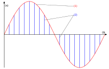
Pulse-amplitude modulation (PAM), is a form of signal modulation where the message information is encoded in the amplitude of a series of signal pulses. It is an analog pulse modulation scheme in which the amplitudes of a train of carrier pulses are varied according to the sample value of the message signal. Demodulation is performed by detecting the amplitude level of the carrier at every single period.
Types
There are two types of pulse amplitude modulation:
- Single polarity PAM: In this a suitable fixed DC bias is added to the signal to ensure that all the pulses are positive.
- Double polarity PAM: In this the pulses are both positive and negative.
Pulse-amplitude modulation is widely used in modulating signal transmission of digital data, with non-baseband applications having been largely replaced by pulse-code modulation, and, more recently, by pulse-position modulation.
In particular, all telephone modems faster than 300 bit/s use quadrature amplitude modulation (QAM). (QAM uses a two-dimensional constellation).
The number of possible pulse amplitudes in analog PAM is theoretically infinite. Digital PAM reduces the number of pulse amplitudes to some power of two. For example, in 4-level PAM there are possible discrete pulse amplitudes; in 8-level PAM there are possible discrete pulse amplitudes; and in 16-level PAM there are possible discrete pulse amplitudes.
Uses
Ethernet
Some versions of the Ethernet communication standard are an example of PAM usage. In particular, 100BASE-TX and BroadR-Reach Ethernet standard, use three-level PAM modulation (PAM-3), 1000BASE-T Gigabit Ethernet uses five-level PAM-5 modulation[1] and 10GBASE-T 10 Gigabit Ethernet uses a Tomlinson-Harashima Precoded (THP) version of pulse-amplitude modulation with 16 discrete levels (PAM-16), encoded in a two-dimensional checkerboard pattern known as DSQ128.
Photo biology
The concept is also used for the study of photosynthesis using a specialized instrument that involves a spectrofluorometric measurement of the kinetics of fluorescence rise and decay in the light-harvesting antenna of thylakoid membranes, thus querying various aspects of the state of the photosystems under different environmental conditions.[2]
Electronic drivers for LED lighting
Pulse-amplitude modulation has also been developed for the control of light-emitting diodes (LEDs), especially for lighting applications.[3] LED drivers based on the PAM technique offer improved energy efficiency over systems based upon other common driver modulation techniques such as pulse-width modulation (PWM) as the forward current passing through an LED is relative to the intensity of the light output and the LED efficiency increases as the forward current is reduced.
Pulse-amplitude modulation LED drivers are able to synchronize pulses across multiple LED channels to enable perfect colour matching. Due to the inherent nature of PAM in conjunction with the rapid switching speed of LEDs it is possible to use LED lighting as a means of wireless data transmission at high speed.
Digital television
The (mostly) North American Advanced Television Systems Committee standards for digital television uses a form of PAM to broadcast the data that makes up the television signal. This system, known as 8VSB, is based on a three-level PAM like 100BASE-TX, but uses additional processing to suppress one sideband and thus make more efficient use of limited bandwidth. Using a single 6 MHz channel allocation, as defined in the previous NTSC analog standard, 8VSB is capable of transmitting 32 Mbit/s. After accounting for error correcting codes and other overhead, the data rate in the signal is 19.39 Mbit/s.
See also
| Wikimedia Commons has media related to Pulse amplitude modulation. |
- Amplitude-shift keying
- Carrier Sense Multiple Access
- Pulse-code modulation
- Pulse-position modulation
- Pulse-width modulation
- Pulse-density modulation
- Pulse forming network
- pulse width
- Quadrature amplitude modulation
- 8VSB
References
- ↑ George Schroeder (2003-04-01). "What PAM5 means to you". EDN. Retrieved 2015-03-02.
- ↑ Schreiber, Ulrich (2004). Pulse-Amplitude-Modulation (PAM) Fluorometry and Saturation Pulse Method: An Overview. Dordrecht: Springer Netherlands. pp. 279–319. ISBN 978-1-4020-3217-2. Retrieved 2015-02-02.
- ↑ im Whitaker (January 2006). “Closed-loop electronic controllers drive LED systems”. LED Lights Magazine. Retrieved 2015-03-02.
