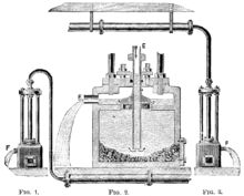
Steam trap

A steam trap is a device used to discharge condensate and non-condensable gases with a negligible consumption or loss of live steam. Most steam traps are nothing more than automatic valves. They open, close or modulate automatically. The three important functions of steam traps are:
- Discharge condensate as soon as it is formed (unless it is desirable to use the sensible heat of the liquid condensate)
- Have a negligible steam consumption (i.e. being energy efficient)
- Have the capability of discharging air and other non-condensable gases.
Basic operation
The simplest form of steam trap is a disc or short solid pipe nipple with a small hole drilled through it installed at the lowest point of the equipment. Since steam condensate will collect at the lowest point and live steam is about 1200 times greater in volume than this hot liquid, condensate is effectively removed and steam is blocked. However, the vast majority of steam traps in current operation are of the mechanical or thermostatically operated design.
Mechanical and thermostatic steam traps basically open when condensate and inert gases need to be removed, and close when all the condensate is removed. The process repeats when new steam is condensed again and ready to be drained.
Steam traps work best when sized specifically for the application they are used on. Generally, it is better to oversize, as they will still discharge condensate when present and close or obstruct for live steam. However an oversized steam trap may wear quickly, waste energy (use steam), and if drastically oversized can cause process issues.
Types
Steam traps can be split into four major types:
There are 4 types of steam trap:
- Mechanical traps. They have a float that rises and falls in relation to condensate level and this usually has a mechanical linkage attached that opens and closes the valve. Mechanical traps operate in direct relationship to condensate levels present in the body of the steam trap. Mechanical steam traps have a typical service of life of 3 years. Inverted bucket and float traps are examples of mechanical traps. Float traps are classified into "free ball float traps" and "lever ball float traps".
- Temperature traps. They have a valve that is driven on / off the seat by either expansion / contraction caused by temperature differ from mechanical traps in that their design requires them to hold back some condensate waiting for it to cool sufficiently to allow the valve to open. In some exceptional circumstances this is not desirable if condensate needs to be removed as soon as it is formed. According to best practices to save energy and reduce CO2 emissions, in most of applications (like tracing lines) it is universally accepted that condensate must be removed 40 ºC (104 ºF) below saturation temperature. This best practice is only possible by using temperature operated traps. Thermostatic traps, Bi-Thermostatic traps and bimetallic traps are examples of temperature operated traps.
- Thermodynamic (TD) traps. Thermodynamic traps work on the difference in dynamic response to velocity change in the flow of compressible and incompressible fluids. As steam enters, static pressure above the disk forces the disk against the valve seat. The static pressure over a large area overcomes the high inlet pressure of the steam. As the steam starts to condense, the pressure against the disk lessens and the trap cycles. This essentially makes a TD trap a "time cycle" device: it will open even if there is only steam present, this can cause premature wear. If non-condensable gas is trapped on top of the disc, it can cause the trap to be locked shut.
- Venturi Nozzle traps. They work based on the two-phase flow to remove condensate from steam systems. Steam and condensate pass through multiple stages. The mechanical design of this pugador is extremely simple and does not include any flow control element, so its correct sizing is very critical and it is obvious that any safety factor in size leads to loss of steam. "The denser liquid (condensate) throttles the venturi nozzle, which keeps the steam from escaping. Erosive eddy currents are eliminated and any contamination is carried away with the condensate. Because condensate is created continuously in a working steam system, the condensate continuously chokes the nozzle from losing steam as condensate is removed continuously".
References
External links
- Steam Trap Monitoring - Bitherm Sistemas.
- Understanding Steam Traps - American Institute of Chemical Engineers (AIChE)
- Steam Trapping, an overview - Spirax Sarco Limited.
- Steam Basics - Armstrong International, Inc.
- Steam Trap Types - US Department of Energy Federal Energy Management Program - broken link!
- What Types of Steam Traps Can You Insulate? - Thermaxx Jackets
- The History of Steam Traps - TLV International, Inc.