Globe valve


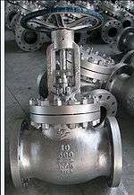
A globe valve, different from ball valve, is a type of valve used for regulating flow in a pipeline, consisting of a movable disk-type element and a stationary ring seat in a generally spherical body.[1]
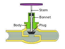
Globe valves are named for their spherical body shape with the two halves of the body being separated by an internal baffle. This has an opening that forms a seat onto which a movable plug[2] can be screwed in to close (or shut) the valve. The plug is also called a disc or disk.[3][4] In globe valves, the plug is connected to a stem which is operated by screw action using a handwheel in manual valves. Typically, automated globe valves use smooth stems rather than threaded and are opened and closed by an actuator assembly.
Information
Although globe valves in the past had the spherical bodies which gave them their name, many modern globe valves do not have much of a spherical shape. However, the term globe valve is still often used for valves that have such an internal mechanism. In plumbing, valves with such a mechanism are also often called stop valves since they don't have the global appearance, but the term stop valve may refer to valves which are used to stop flow even when they have other mechanisms or designs.
Globe valves are used for applications requiring throttling and frequent operation. For example, globe valves or valves with a similar mechanism may be used as sampling valves, which are normally when liquid samples are being taken. Since the baffle restricts flow, they are not recommended where full, unobstructed flow is required.
Globe valves are always reverse seated.
Parts of a typical globe valve

Body
The body is the main pressure containing structure of the valve and the most easily identified as it forms the mass of the valve. It contains all of the valve's internal parts that will come in contact with the substance being controlled by the valve. The bonnet is connected to the body and provides the containment of the fluid, gas, or slurry that is being controlled.
Globe valves are typically two-port valves, although three port valves are also produced mostly in straight-flow configuration. Ports are openings in the body for fluid flowing in or out. The two ports may be oriented straight across from each other or anywhere on the body,[5] or oriented at an angle (such as a 90°).[6] Globe valves with ports at such an angle are called angle globe valves. Globe valves are mainly used for corrosive or high viscous fluids which solidify at room temperature. This is because straight valves are designed so that the outlet pipe is in line with the inlet pipe and the fluid has a good chance of staying there in the case of horizontal piping. In the case of angle valves, the outlet pipe is directed towards the bottom. This allows the fluid to drain off. In turn, this prevents clogging and/or corrosion of the valve components over a period of time. A globe valve can also have a body in the shape of a "Y". This will allow the construction of the valve to be straight at the bottom as opposed to the conventional pot type construction (to arrange bottom seat) in case of other valves. This will again allow the fluid to pass through without difficulty and minimizes fluid clogging/corrosion in the long term.
Bonnet
The bonnet provides a leakproof closure for the valve body. The threaded section of the stem goes through a hole with matching threads in the bonnet. Globe valves may have a screw-in, union, or bolted[5] bonnet. Screw-in bonnet is the simplest bonnet, offering a durable, pressure-tight seal. Union bonnet is suitable for applications requiring frequent inspection or cleaning. It also gives the body added strength. A bonnet attached with bolts is used for larger or higher pressure applications. The bonnet also contains the packing, a wearable material that maintains the seal between the bonnet and the stem during valve cycling.
Plug or disc (disk)
The closure member of the valve, plugs are connected to the stem which is slid or screwed up or down to throttle the flow. Plugs are typically of the balance or unbalanced type. Unbalanced plugs are solid and are used with smaller valves or with low pressure drops across the valve. The advantages are simpler design, with one possible leak path at the seat and usually lower cost. The disadvantages are the limited size; with a large unbalanced plug the forces needed to seat and hold the flow often becomes impractical. Balanced plugs have holes through the plug. Advantages include easier shut off as the plug does not have to overcome static forces. However, a second leak path is created between the plug and the cage, and cost is generally higher.
Stem
The stem serves as a connector from the actuator to the inside of the valve and transmits this actuation force. Stems are either smooth for actuator controlled valves or threaded for manual valves. The smooth stems are surrounded by packing material to prevent leaking material from the valve. This packing is a wearable material and will have to be replaced during maintenance. With a smooth stem the ends are threaded to allow connection to the plug and the actuator. The stem must not only withstand a large amount of compression force during valve closure, but also have high tensile strength during valve opening. In addition, the stem must be very straight, or have low run out, in order to ensure good valve closure. This minimum run out also minimizes wear of the packing contained in the bonnet, which provides the seal against leakage. The stem may be provided with a shroud over the packing nut to prevent foreign bodies entering the packing material, which would accelerate wear.v
Cage
The cage is a part of the valve that surrounds the plug and is located inside the body of the valve. Typically, the cage is one of the greatest determiners of flow within the valve. As the plug is moved more of the openings in the cage are exposed and flow is increased and vice versa. The design and layout of the openings can have a large effect on flow of material (the flow characteristics of different materials at temperatures, pressures that are in a range). Cages are also used to guide the plug to the seat of the valve for a good shutoff, substituting the guiding from the bonnet.
Seat
The seat ring provides a stable, uniform and replaceable shut off surface. Seat are usually screwed in or torqued . This pushes the cage down on the lip of the seat and holds it firmly to the body of the valve. Seat may also be threaded and screwed into a thread cut in the same area of the body. However this method makes removal of the seat ring during maintenance difficult if not impossible. Seat rings are also typically beveled at the seating surface to allow for some guiding during the final stages of closing the valve.
Economical globe valves or stop valves with a similar mechanism used in plumbing often have a rubber washer at the bottom of the disc for the seating surface, so that rubber can be compressed against the seat to form a leak-tight seal when shut.
See also
References
- ↑ McGraw-Hill Dictionary of Scientific and Technical Terms. McGraw-Hill Companies (April 25, 2007). "Globe Valve". Check date values in:
|year= / |date= mismatch(help) - ↑ Process Instrumentation (Lecture 8): Control valves
- ↑ http://www.answers.com/topic/globe-valve under heading "McGraw-Hill Professional – Architecture" diagram shows disc
- ↑ Globe Valve Disks
- 1 2 http://www.answers.com/topic/globe-valve under heading "McGraw-Hill Professional – Architecture" diagram shows disc. See diagram of "straight body" globe valve with bolted bonnet here.
- ↑ http://www.tpub.com/content/doe/h1018v2/css/h1018v2_37.htm Globe Valve Disks. See diagram of angle globe valve here.
External links
- Control Valve Handbook – Fisher Controls International (4th Edition) – a complete 297-page online book.
- Process Instrumentation (Lecture 8): Control valves – an article from a University of South Australia website.